PFI Panel Wiring Diagram: Simplify Your Power Factor Correction Setup Power factor correction unit wiring diagram power factor cor
Power factor correction is a critical aspect of modern electrical systems, aimed at improving energy efficiency and reducing operational costs. Understanding and implementing effective power factor correction techniques is essential for electrical engineers and facility managers alike. In essence, power factor refers to the ratio of real power (kW) to apparent power (kVA) in an electrical circuit. An ideal power factor is close to 1.0, indicating maximum efficiency. However, inductive loads, such as motors and transformers, can cause a lagging power factor, drawing reactive power that does not contribute to useful work but increases the overall current flow. Poor power factor can lead to several problems, including increased energy bills, overloaded equipment, voltage drops, and penalties imposed by utility companies. To mitigate these issues, power factor correction methods are employed, typically involving the installation of capacitors to counteract the inductive reactance. These capacitors provide reactive power locally, reducing the burden on the utility grid and improving the power factor closer to unity. Selecting the appropriate power factor correction equipment is crucial. Factors to consider include the size of the load, the existing power factor, the desired power factor, and the harmonic content in the system. Fixed capacitors can be used for relatively constant loads, while automatic power factor correction (APFC) systems are more suitable for fluctuating loads. APFC systems use a power factor relay to monitor the power factor and automatically switch capacitors in and out of the circuit as needed. The proper wiring and configuration of power factor correction equipment are essential for its safe and effective operation. Incorrect wiring can lead to equipment damage, system instability, and even safety hazards. Therefore, it is important to consult with qualified electrical engineers and technicians to ensure that the installation is carried out according to applicable standards and best practices. Furthermore, regular maintenance and monitoring of the power factor correction system are necessary to ensure its continued performance and reliability. This includes checking capacitor banks for signs of degradation, verifying the accuracy of the power factor relay, and monitoring the overall power factor of the facility. By proactively addressing any issues, electrical engineers can ensure that the power factor correction system continues to deliver optimal benefits. Ultimately, effective power factor correction is a key component of a comprehensive energy management strategy. By improving power factor, businesses and organizations can reduce energy consumption, lower operating costs, and minimize their environmental impact. As energy prices continue to rise and sustainability becomes increasingly important, power factor correction will play an even greater role in optimizing the performance of electrical systems.
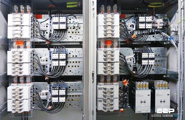
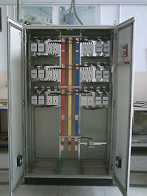
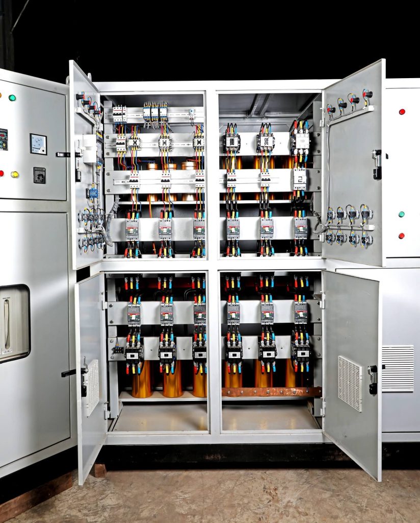
190 KVAR PFI Panel

This image depicts a 190 KVAR Power Factor Improvement (PFI) Panel. PFI panels are designed to improve the power factor of electrical systems, which reduces energy costs and improves efficiency. This particular panel, manufactured by PowerSonic, is designed to correct power factor for large industrial loads. The panel appears to be a robust, self-contained unit, housing the necessary capacitors and control equipment to automatically adjust power factor. Components of note in a PFI Panel are capacitor banks, designed to supply reactive power and improve the power factor by counteracting the effects of inductive loads. Automatic switching gears adjust the capacitor banks to match the load demands. It also includes a power factor relay, which monitors the power factor and automatically switches capacitors in and out of the circuit as needed to maintain a target power factor. The unit will reduce reactive power demand from the grid, leading to lower utility bills and reduced losses in the electrical system. Effective power factor correction can also extend the lifespan of electrical equipment by reducing stress on the distribution system and enhancing the reliability of the power supply.
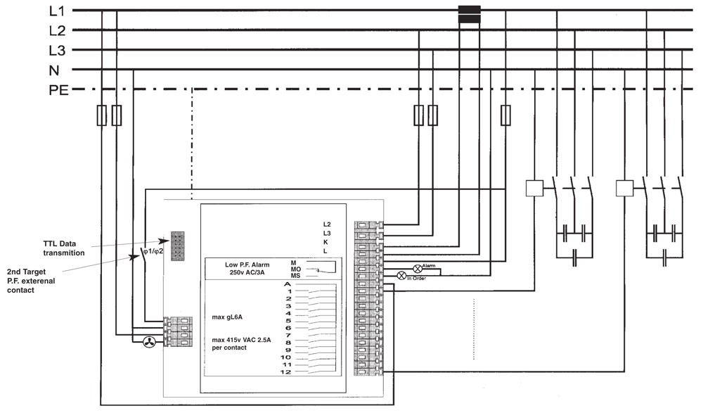
Wiring of power factor relay on LV and MV side
This image provides circuit diagrams illustrating the wiring of a power factor relay on both the Low Voltage (LV) and Medium Voltage (MV) sides of an electrical system. Power factor relays are essential components in automatic power factor correction (APFC) systems, responsible for monitoring the power factor and controlling the switching of capacitor banks to maintain the desired power factor level. The diagrams show the connections for both LV and MV systems, demonstrating the different wiring configurations and components required for each voltage level. These may include current transformers (CTs) and voltage transformers (VTs) to step down the current and voltage to levels suitable for the relay. Correct wiring is crucial for the proper functioning of the power factor relay and the overall APFC system. Incorrect wiring can lead to inaccurate power factor readings, improper capacitor bank switching, and potential damage to equipment. The accuracy of the power factor relay is paramount for efficient power factor correction. Regular calibration and testing are recommended to ensure the relay provides precise measurements and reliable control. Proper power factor relay wiring ensures efficient capacitor bank operation and improves power factor in electrical systems. This reduces energy losses, enhances equipment efficiency, and contributes to a stable and reliable power supply, benefiting both the facility and the utility grid.
If you are looking for Power Factor Correction | EnergyAustralia you've came to the right place. We have 25 Images about Power Factor Correction | EnergyAustralia like PFI Panel Wiring Diagram | Power Factor Improvement | PFI Panel Circuit, Power Factor Panel (PFI) – HRA Switchgear Pvt Ltd. and also Pfi Panel Wiring Diagram - Ecoced. Here it is:
Power Factor Correction | EnergyAustralia
 www.energyaustralia.com.au
 correction energyaustralia
Wiring Of Power Factor Relay On LV And MV Side (circuit Diagrams) | EEP
electrical-engineering-portal.com factor power relay wiring diagrams circuit kaise kare lv mv side eep
Power Factor Panel (PFI) – HRA Switchgear Pvt Ltd.
 hraswitchgear.com
 How To Calculate Power Factor Correction? - EEE COMMUNITY
 eeecommunity.blogspot.com
 power factor correction how calculate electrical engineering books board eeecommunity eee choose updates saved
3 Phase Power Factor Circuit Diagram
 diagramlibdunagan.z19.web.core.windows.net
 Pfi Panel Wiring Diagram - Ecoced
 ecoced83.blogspot.com
 Apfc Panel Connection Diagram
 wiringdiagramall.blogspot.com
 Pfi Panel Wiring Diagram - Ecoced
 ecoced83.blogspot.com
 190 KVAR PFI Panel | PowerSonic
powersonicbd.com PFI Panel Wiring Diagram | Power Factor Improvement | PFI Panel Circuit
 learningengineering1994.blogspot.com
 PFI Panel Circuit Diagram | Power Factor Improvement Diagram | Voltage Lab
 www.voltagelab.com
 PFI Panel Circuit Diagram | Power Factor Improvement Diagram | Voltage Lab
 www.voltagelab.com
 PFI Panel – Asha Power Technology Ltd.
 www.ashapower.com.bd
 Power Factor Correction Panels
 www.alfanar.com
 factor power correction panels pfc equipment electrical products
Power Factor Correction Capacitor Wiring Diagram Connection
 manualcanadiaklshcf.z21.web.core.windows.net
 Power Factor Correction Unit Wiring Diagram Power Factor Cor
 saetti9lvguide.z14.web.core.windows.net
 Tips For Power Factor Correction And Good Protection Of Capacitors | EEP
 electrical-engineering-portal.com
 factor correction capacitors capacitor
Capacitor Panel Circuit Diagram - Circuit Diagram
 www.circuitdiagram.co
 Power Factor Panel Wiring Diagram Three Phase Ht Power Facto
 saetti9lvguide.z14.web.core.windows.net
 600KVAr Automatic Power Factor Correction - TECO GROUP - Automation
 tecogrp.com
 power automatic panel factor correction panels control tecogrp
CR4 - Thread: Automatic Power Factor Correction Panel
 cr4.globalspec.com
 capacitor power banks system correction panel factor automatic two part voltage switchgear low always means optimal would be
Simple Power Factor Correction Circuit Diagrams
 www.circuitdiagram.co
 Automatic Power Factor Correction Capacitor Panel At ₹ 30000
 www.indiamart.com
 panel power correction factor automatic capacitor
PFI PANEL – Techno Venture Ltd.
 www.tvl-bd.com
 Pfi Panel Wiring Diagram - Ecoced
Power factor correction unit wiring diagram power factor cor. Simple power factor correction circuit diagrams. How to calculate power factor correction?